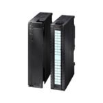
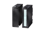
PLC Module Product Introduction
Ce API module is tailored for high-reliability industrial control scenarios, with core features that prioritize system stability and operational flexibility. Notamment, this PLC module supports the S7-400H redundant system—this redundancy ensures seamless switching to a backup unit if the main system encounters faults, avoiding unexpected downtime in critical production processes.
En outre, it supports online hot swapping: users can replace or maintain components without shutting down the entire control system, which significantly reduces maintenance-related interruptions and improves overall operational efficiency. In terms of configuration, it is compatible with STEP7 and TIA Portal (Botu) configuration software, allowing engineers to use familiar tools for programming, parameter setting, and system debugging—simplifying the setup process and lowering operational thresholds.
En outre, it supports I/O redundancy, which means key input/output channels have backup paths. This design prevents single-point I/O failures from affecting the entire system, further enhancing the PLC module’s fault tolerance. Beyond that, it integrates system diagnosis functions for power failure, short circuit, and open circuit issues: it can quickly detect these anomalies and send alerts, helping maintenance personnel locate and resolve problems promptly, reducing troubleshooting time.
With these features, this PLC module is well-suited for industrial automation systems that demand high availability and stability, such as those in chemical processing, power generation, and continuous manufacturing lines.
| Specification parameters | Model no | CPU SR20 AC/DC/RLY |
| Article No | E7 288-1SR20-0AA1 | |
| Description | Standard CPU SR20, Relay |
| Conventional norm | Dimensions WxHxD(mm) | 90×100×81mm |
| Power Consumption | 14W | |
| Available current(SM bus) | max.1400mA | |
| Available current(24V DC) | max.300mA |
| CPU Features | Program Memory (KB) | 30 |
| Data Memory (KB) | 12 | |
| Retentive Memory (KB) | 12 | |
| Data Preservation | permanent | |
|
Built-in I/O Built-in I/O |
||
| Digital Input/Output | 12 saisir /8 output | |
| Analog Input/Output | ||
| Process Image Size | 256-bit input (je)/256-bit output (Q) | |
| Analog Image | 56 words input (AI) 56 words output (AQ) | |
| Expansion Modules Allowed | Up to 6 modules | |
| High speed counter (total) | 6 in total | |
|
.Single Phase .Single Phase |
4 200KHz + 2 30KHz | |
| .Quadrature Phase | 2 100KHz + 2 20KHz | |
| Pulse output | – | |
| Timer | Non-holding (or not retained) (TON, TOF):192 Holding (or retained) : 64 |
|
| Counters | 256 | |
| Bit memory(M) | 256 bits | |
| Cycle Interrupt | 2 in total, T32 and T96 have a resolution of 1ms | |
| Interrupt Edge | 4 up and 4 down | |
| Real Time Clock | Usually 7 jours, at least 6 days at 25°C | |
| Memory card | support | |
| Signal expansion boar | Soutien |
| Performance/ Processing Time |
.Boolean |
0.35uS/instruction |
| .Moving Word Operations | 1.2uS/instruction | |
| .Floating Point | 1.7uS/instruction |
| Communications Built-in | Ports | Ethernet: 1 Body serial port: 2(DB9-RS485) DB board serial port: 1(CM01-RS485-RS232) |
| HMI Connections | Ethernet: 8 connections Serial port: 4 connections |
|
| Programming (PG) | 1 connection | |
| Ethernet | ||
| CPU(PUT/GET) | 8 clients and 8 servers connections | |
| Open type communication | 8 active and 8 passive connections | |
| Data Transmission rate | Ethernet:10/100 Mb/s; RS485 System Protocol:9600,19200 et 187500 b/s; RS485 free port:1200 à 115200 b/s |
|
| Isolation | Ethernet:Transformer isolation,1500VCC; RS485:None |
|
| Cable type | Ethernet:CAT5e Shielded cable
RS485:PROFIBUS Network cable |
| Pouvoir | Tension d'entrée | 85-264VCC |
| Input current(CPU only) | 130mA(w/o 300mA power supply output of the sensor)when CPU only at 120V AC 250mA(w/ 300mA power supply output of the sensor)when CPU only at 120V AC 80mA(w/o 300mA power supply output of the sensor) when CPU only at 240V AC 150mA(w/ 300mA power supply output of the sensor)when CPU only at 240V AC |
|
| Input current(Includes CPU and all expansion accessories) | 300mA at 120VAC 190mA at 240VAC | |
| Inrush Current (Max.) | 9.3A at 264VDC | |
| Sensor voltage | 20.4-28.8VCC | |
| Isolation | ||
| Input to logic | 1500VAC,1min | |
| Sensor to logic | Not isolated |
| Digital Input | Number of Inputs | 12 |
| Input type | The sinking /sourcing type(IEC type 1 sinking) | |
| Allowable Continuous Voltage | Max.30VDC | |
| Surge voltage(Max.) | 35V DC, lasting 0.5s | |
| Logic 1 signal(Min.) | 15V DC when the current is 2.5mA | |
| Logic 0 signal(Max.) | 5V DC when the current is 1mA | |
| Optical Isolation (field side and logic side) | 500V AC lasting 1.0min | |
| Isolation group | 1 | |
| Filter time | Each channel can be separately selected(point I0.0 to I1.3): 0.2, 0.4, 0.8, 1.6, 3.2, 6.4 et 12.8 µs; 0.2, 0.4, 0.8, 1.6,3.2, 6.4 and 12.8ms; |
| Digital Output | Number of Outputs | 8 |
| Output type | Relay, dry contact | |
| Voltage range | 5-30VDC or 5-250VAC | |
| Surge Current (Max.) | 7A when power on | |
| Rated Current per each point (Max.) | 2.0UN | |
| Switching Frequency (Max.) | Not recommended | |
| Turn-on delay(Qa.0-Qa.3) | Up to 10ms | |
| Turn-off delay(Qa.4-Qa.7) | Up to 10ms | |
| Optical Isolation (field side and logic side) | 500V AC lasting 1.0min | |
| Contact Lifetime | ||
| non-loaded | 10,000,000 cycles | |
| Rated load | 10,000 cycles |